Walnut Hue
Certainly, (American) walnut comes in many hues. I've seen some from the farm here that is almost butternut yellow whereas heartwood can be almost dark chocolate for large timber. I had heard some very early props were heart pine (Pinus palustris).
If I can manage a volumetric estimate given your prop dimensions, I should be able to calculate a weight and weight range. Since the density of various wood species (and their % water content vs season), is well known, it may be possible to simply weigh the prop to rule out some wood types.
Yes: walnut is probably most likely.
I wonder whether there are consistent hue differences between American and European/French walnut.
-@pete
-
Between walnut, mahogany and pine I would be almost certain that mine is walnut. It's not dark walnut, but is very similar in color and grain to this British Avro prop. I think an amber colored shellac makes it look "different".Leave a comment:
-
Hi,
Just true very quick words...
1 I think there were too many props designed between 1907 and 1914 (while WW1, it is another story) to use these data: more than 50 brands, each with its own shape.Originally posted by drrivah View Post
2 Some first Ratmanoff designs do show sections with a "sigmoid" profile.
3 What kind of Ratmanoff are you looking at? Before 1914, all are constructed with all laminations except one (eventually two) going up to the tip on intrado side (which can be not the side facing the pilot, because many props among the first ones are pusher).
4 From memory, all constructed with walnut or mahogany. I will check with my books at the end of the week.
Regards,
PMLeave a comment:
-
Helice
The Park treatise has been the basis for my designs and speculations for a few years, along with Durand's 1917 NACA reports (No. 3) and other original papers. I believe the Ratmanoff most resembles Durant's "A1S1F1" model, the source of my proposed Ratmanoff model data and calculations above.
Park's book is a nice handbook, but it doesn't really delve into why a designer might increase, then decrease the face pitch (angle of incidence nonlinearly applied) at certain radii. That's what I get when I model the Ratmanoff.
The prop disc from ~50-90% radius seems to show a negative angle of incidence if P=0760. Could be measurement uncertainty or perhaps an intentional design feature like the very interesting structure of the Garuda props.
There are a few series of propeller airfoils designed in the period between 1908-1917 from NPL, Eiffel, Goettingen and the RAF. I believe coordinates on all are publicly accessible through Univ. Illinois. If one can identify the airfoil dimensions and thereby, the airfoil series, of an unidentified prop, you may be able to more precisely date a propeller.
For example, if Eiffel's series wasn't published before 1910 and his sections are used, that might date the prop to 1910 or after, yes?
And BTW, is there evidence that Eiffel, Ratmanoff and Drzewiecki were all acquainted with each other, as is common among academic engineers and scientists working in the same or nearby cities?
If you return to the Wright brother's original correspondence & letters, yes, I do believe they would have used Home Depot, had it existed in 1900-1903.
Specifically look at their sourcing for hinges, for example.
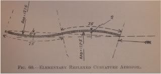
Dave's end-on photo of the Ratmanoff holds a surprise (for me, at any rate): I do not believe the tip is warped. Specifically, there are airfoils that are shaped somewhat sigmoidally known as "reflexed curvature" (see Judge [Properties of Airfoils and Aerodynamic Bodies, Selwyn 1917] Figure 60, below). Interestingly enough, Eiffel showed that such a profile creates lift above 6 degrees incidence, exactly what Dave measured. Could be coincidence.
Why did Drzewiecki specify such a reflexed curvature for his prop tip on the Ratmanoff? (Answer is not in Park's book, BTW).Yes, I agree there is some sophistication there about fluid dynamic properties and prop tips.
A few other structural questions:
-does the hub bore of the Ratmanoff have slightly larger bore on both faces
than the central lumen of the bore? (compression space)
-the Ratmanoff model I'm looking at predicts lamination joints on the back (engine side) at about radii 260mm, 390mm and 611mm, and then no face laminations from 611mm out to the tip. Yes?
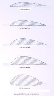
-Finally, the usual wood specified is ash, walnut or mahogany, but the Ratmanoff looks lighter, maybe heart pine, maple or poplar. The distal tips seem to have been covered with doped linen beyond the decal, preventing the outer blades from "sunburning" which happens to cut wood exposed to sunlight.
Provide an email and I would be happy to send the model parameters for critique.
Best,
-@pete
 Last edited by drrivah; 01-31-2012, 08:27 AM.
Leave a comment:
-
Just a quick pass through here to see where is now this very interesting thread...
@Dave: "So how far "up" does a 6 degree angle go in a distance of about 660 cms?" The answer is 660 x tangent*** (6°), that is 660 x 0.105 = 69.3 cm. This number is a geometrical pitch. Numbers given by Ratmanoff are "aerodynamical" pitch: that is the true displacement of the aircraft for one turn of the engine, and he rightly calls that "advance by turn". He can't give a pitch, because his propellers have not an identical geometrical pitch along the blade.
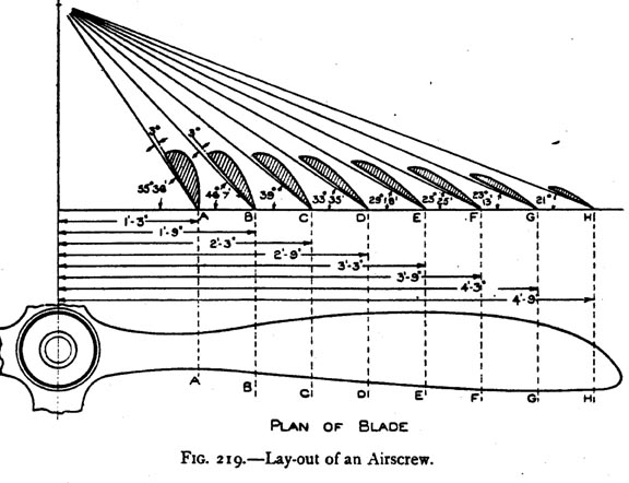
Note that on your picture (Plan of a blade, fig 219), the geometrical pitch increases regularly along the blade because there is a constant 3° angle added to the distance proportional angle indicated by the angles written for each section.
But it is NOT the case for Ratmanoff props. The geometrical pitch increases from hub to tip, but the increase is not regular. On a figure like this for a Ratmanoff, the "added angle of 3°" is different for each section.
Note also there have to be a mistake or a miswriting (or I misread the numbers) for the "F" section: the angle can't be 25°25', but higher, around 25°55'.
*** You can use the Windows calculator (chose the "scientific display") to compute all this. Don't forget to tick the "degrees" option (by default, it is the "Radians" option which is chosen: 360°=2 x 3.14 radians). And you have also to convert sexagecimal degrees (° ' ") in decimal degrees (add to degrees number the minutes divided by 60 and seconds divided by 3600).
@Pete: Without being pedantic, I think you can read this to see how was the "thinking" about propellers in first years: http://www.archive.org/details/treat...rscr00parkuoft . It is from 1920, so already far from the 1907-1914 years, but I don't know anything in English from the first propeller making years. You will see this is not about the story of a guy who buy some boards at Home Depot... Drzewiecki writings from 1909 are as sophisticated
Not so quick pass!
Regards,
And, one more time, sorry for my rude English,
PMLeave a comment:
-
Helice
Dave:
At D2080 P076 with typical airfoil sections I get:
Most of blade is P076 but there are some non-linear adjustments
that may be due to measurement error or intended design.
-@peteLeave a comment:
-
Prop Math
Dave:
I agree you can measure the angle at any radius and get a first guess of pitch.
The diagram you posted is very complicated (but complete in terms of engineering). It has three or four families of information going on: to define the form of a prop without a diagram you have to take one family of parameters at a time and nail the family down before proceeding.
Since the blade is relatively narrow (compared to Chauviere), the blade edges are nearly parallel and the "intrados" side is flat bottomed, the most likely airfoil family is as follows:
The family is mathematically defined, but don't worry about that yet.
To ask whether you have the right family of airfoils on a prop, you need only measure the thickest part of the airfoil at any radius (defined).
For example,
At radius 231mm, 50mm should be the thickest part of the airfoil. Easy to measure with a curved caliper and metric ruler.
If wrong, no need to do more (back to the drawing board). If right, look a little farther out at:
Radius 404mm: the fat part should be 31mm thick.
And so on.
-@peteLast edited by drrivah; 01-29-2012, 06:24 PM.Leave a comment:
-
I'm not sure how to process all those figures. I would think, however, that a single angle at a known distance from the center would give you a rough idea of pitch and that all measurements along the blade would be predictable based on that estimate.
In this case if you assume the angle of the chord is 6 degrees at a distance of 105 cm, then the pitch calculated on that basis would be extrapolated to any point along the length of the blade, as in this diagram:
Certainly just by looking at this Normale propeller in the picture at the tip I would consider it to be a very FLAT pitch compared to most others.
I've forgotten any trigonometry, but an angle of 6 degrees would "climb" a specific distance over the course of the circumference of a single turn, and that circumferential distance is a simple function of the radius of 105 cm. (PiXD, or 210 x 3.14 = 660 cm ). So how far "up" does a 6 degree angle go in a distance of about 660 cms?Leave a comment:
-
Helice Normale
Hi Dave:
...at the risk of throwing (more) gasoline on the fire...
OK, and at risk of exposing rank ignorance, time for some testable specifics. I made a few assumptions about the Ratmanoff form and prop sections and have run a few rough numbers to test whether model 1 or model 2 is closer to the real prop.
Ratmanoff D2080, Pitch Unknown.
RADIUS Predicted Face Angle Predicted Max Section Thickness
MODEL1 MODEL2
231mm 39 deg 33 deg 50mm
404mm 26.8 deg 18.5 deg 31mm
578mm 20.5 deg 9 deg 25mm
751mm 8.1 deg 3 deg 22mm
924mm 5.5 deg 1 deg 14mm
1040mm 0-5 deg 0-1 deg 10-14mm
Radius leading edge corner ~1040mm radius= 36mm
Radius training edge corner ~1040mm radius= 54mm
The nice thing about the models is that you have something to measure to say "yes" or "no" or "maybe". Or, back to the drawing board...
On working this exercise so far, I have to retract my skepticism above about how low the overall pitch is. Could actually be "0m76" (ie, 760 mm), which would be astonishing, but I have to bow to the authority of the data however it turns out.
The above was done from measurements and assumptions without assuming
anything about pitch.
Have fun.
Cheers
-@peteLeave a comment:
-
Magnificent obsession!
I along with Bob Gardner wish to say how much this particular thread is truly fascinating. It is greatly appreciated that this site exists, its like a pack of would be sherlock holmes types that are on the hunt for all of the clues, it just gets better and better with each passing day.
That being said, as much as I am involved in the aviation industry on levels that most dont get to enjoy, the little kid in me that has the ability to also poke fun at the aviation world through graphic design and silkscreened textiles ( T-Shirts ) I will now post a photo of an image that I designed about 12 years ago.
Before the replys start as to what this machine is, here are the specs. The front engine is from a B-17, with a 3 bladed hamilton standard with an aero-matic hub. The main rotor is from an aerospatiale lama powered by a turbo mecca turbine. The cock pit is from an air tractor aerial applicator, and the tail rotor is from a bell jet ranger III. The tractor is the model "U" which stands for universal and it was manufactured by Minneapolis-Moline Co.
Each year when I bring these shirts back to the seaplane base at oshkosh, its amazing how many people just get a huge kick and a belly laugh when they see this mating of exotic interconnected mass of meshing gears.
Every circus gets quite when the trapeze act starts, especially when there is no net, think of this as the small clown car that comes out to offer a bit of humor to something so serious and sacred.
Sincerely,
Dennis Hicklin
Seattle WashingtonLeave a comment:
-
I realized that the two angles I showed above might not match up. The first photo is taken end on and the yellow line is probably close to the chord. The 40mm one is showing the rear face, so the angle of the chord line might be slightly different. (Although I think it would be the rear surface that would be used to estimate pitch.)Originally posted by drrivah View PostLeave a comment:
-
Helice
Hi Dave:
"Whoa: way cool".
More on helix math, face angles and what goes in to figuring that, shortly...
-@peteLeave a comment:
-
Hi Dave,
All is unusual about Normale props: Drzewiecki had very special theories. His main one was to make prop with a constant Angle of Attack along the blade of about 2°. Angle has to be computed taking into account the displacement at the expected speed and the direction of the air stream when flying. Very interesting, but those shapes have been quickly discontinued, probably because they were not truly efficient.Originally posted by Dave View Post
Regards,
PM
@drrivah: I will be out for a while, so don't expect answers before end of the next week. I have already seen some of your pictures by looking at the address of the one you posted (right click and "picture properties" gives the PhotoBucket address of your albums. Beware of that ). Nice job!
Leave a comment:
-
Helice prop math
Hi Pierre-Michel:
The point is to understand prop design theory (historical and modern), how it has evolved and how to design props for new (2012) engines.
I am curious to know where, in the inventor's mind, ideas and technical innovation come from.
Regarding lumber, in the U. S. the rough-cut board is labeled and graded in quarters of an inch.
4/4 (26mm)
5/4 (32mm)
6/4 (40mm)
8/4 (51mm)
10/4 (64mm)
12/4 (77mm)
Nominal 1" lumber is sold as 1", if planed and smooth sided, has a final thickness of 3/4" (0.750). Note that a rough cut 26mm board planed to 20mm would be 0.78", close to the 3/4". So, 20mm seems reasonable for stock European lumber planed both sides. My guess is that in 1909, a small inventor would just go over to the 1909 equivalent of Home Depot, and buy a few boards (without wood flaws) off the shelf for his experiments. In the US, they would have been 3/4", in France likely 20mm.
Your measurement on the Levasseur examples is consistent with the idea that prop makers used 26mm lumber planed to 20mm finished thickness.
BTW, investigating old props is like synthetic analytical chemistry: you make some measurements about structure, take a few guesses, come up with a likely structure. To confirm your deductions and experimental guesses, you have to synthesize according to your hypothesis and see if the final design is "right". This may lead the experimeter to understanding structure, at which point he may be tempted to make a "better one".
Thanks.
-@pete
PS: My first experiment is here:
http://s290.photobucket.com/albums/l...ops/?start=all
It is not a copy of a prior historical design: it is new, based on study of prop math and old props, for use possible on a C85 engine. It is pine, and a first model, not meant to be used on an engine. If warranted, a test model would be constructed of walnut, properly balanced and certified.Leave a comment:
-
Actually, the laminations on the Normale prop are unusual. The front and rear thicknesses are 30 mm and the two central boards are 17 mm. The total is 94 mm.
The approximate pitch could be determined using the angle of the blade at the tip, knowing that the distance from the center bore is half the diameter of the propeller. Both of the attached photos are first leveled to the horizontal then the angle at the tip and another one at 40 mm from the center are shown. The rear of the blade is flat throughout - neither convex nor concave in cross section. (Note that the blue template tool remains flat along that surface.)Leave a comment:
Leave a comment: